A Video
Everyone loves a video, so feel free to start here.
Starting With The Actuators
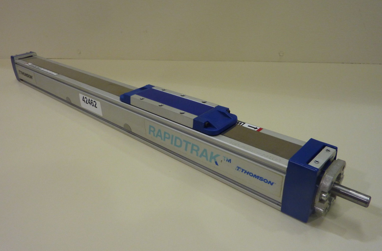
I found some long ballscrew actuators with 19" of travel on ebay, so I did the only natural thing and purchased six of them. They're Thomson actuators, which unfortunately lack some good features for CNC. The ballscrew has a half-inch lead, so that's good news to keep sufficient torque. For starters, they have a fair bit of backlash (play between the engagement with the balls in the ball nut and either side of the three) at 0.003". No doubt, this is off to a bad start. Much worse, though, the actuators lack any true bearing guide. Instead, they have an adjustable (flexure-based) set of Delrin guides for actuation, which ride along in the aluminum-extrusion track. I decided that I would just software-correct the backlash, and double or triple-up the actuators to gain rigidity, and used the actuators as a start to a design.
I had initally planned on a five axis, but the 19" travel was too small for general use on a five-axis. So I opted to take the boring route, making a more pragmatic three-axis machine. I also decided that I would make the machine quickly convertible to a 3D printer, giving me a massive build volume (by writing a custom post-processor, you can 3D print using standard CNC machine controllers such as Mach3). I built this whole machine in around a week, including time waiting for parts, so design only lasted a few hours.
The Design
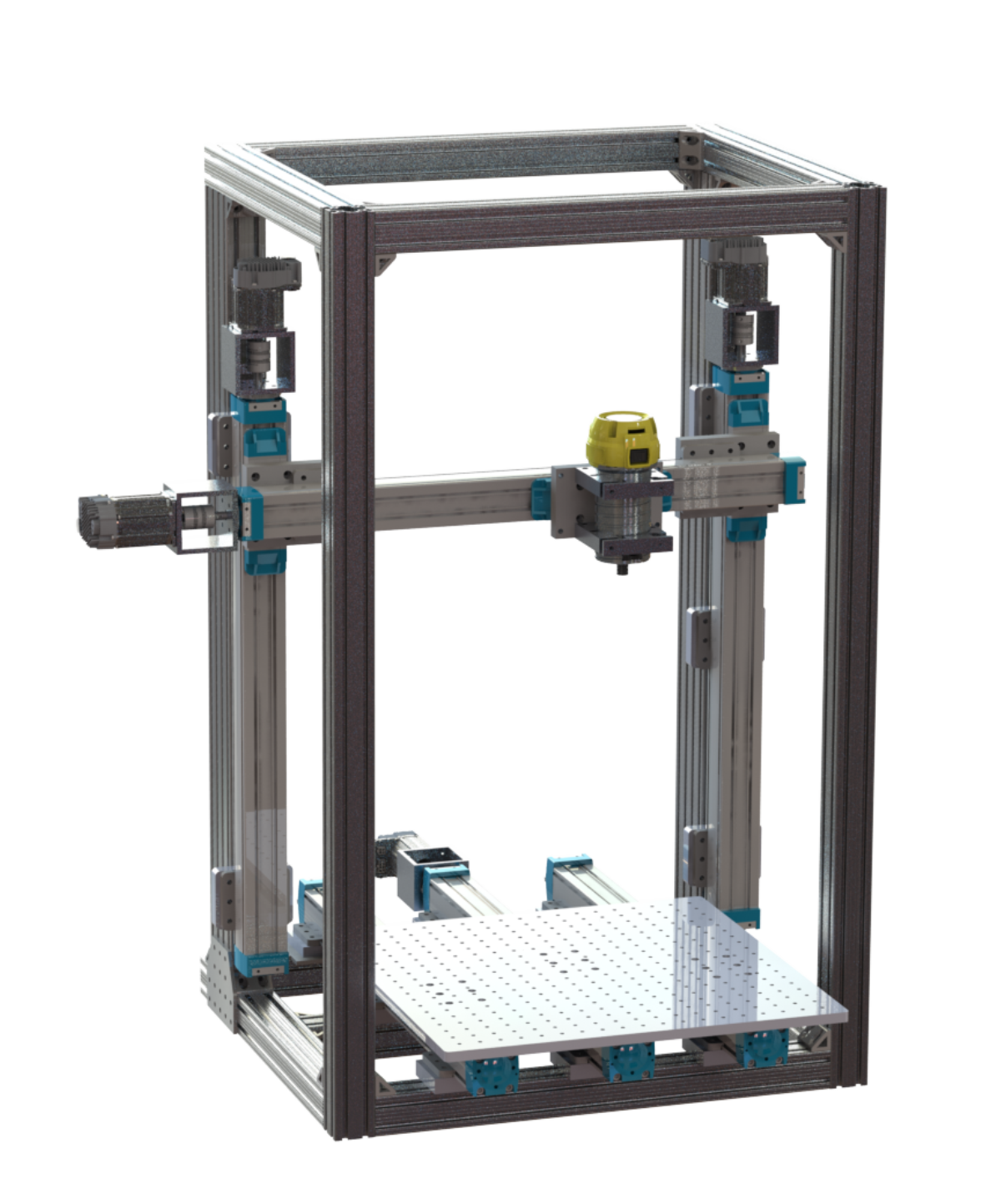
A few hours in SolidWorks and a render later, this is the result. A simple 3-axis CNC machine using six actuators. The first thing you'll probably notice is the massive z-travel. There are a few reasons for this:
Another thing to notice is the use of three different actuators on the Y-axis, but only one motor. To minimize costs, I ripped the ballscrews out of two of these actuators (these actuators were absurdly cheap... making this more cost-effective than buying linear guides) and stored them away for later.The outer two actuators are shifted forward by about 6 inches (you can see this by looking at the bolt holes on the top of the Y-axis plate). This was necessary to sufficiently improve rigidity, and the motor had no problem overcoming the additional force. The astute amongst you might have also noticed a second actuator on in the X-axis in the other pictures and the video. It turned out that the X-axis was not nearly rigid enough, so I bought another actuator, ripped the ballscrew out, and was able to dramatically improve rigidity.
Despite the cost, I prefer to run servoes over steppers whenever possible. Frankly, I just don't find it worth the time to deal with lost steps, and would rather just purchase a servo for most tasks, especially early prototyping. In this design I'm using Teknic's ClearPath Servoes, which can be had for as low as $257 a motor. Considering they have a driver on-board, I think this is very worthwhile. You can control feedback, track force, carefully tune them, torque limit, and much more with these servoes, making them a much better choice over steppers for most tasks.
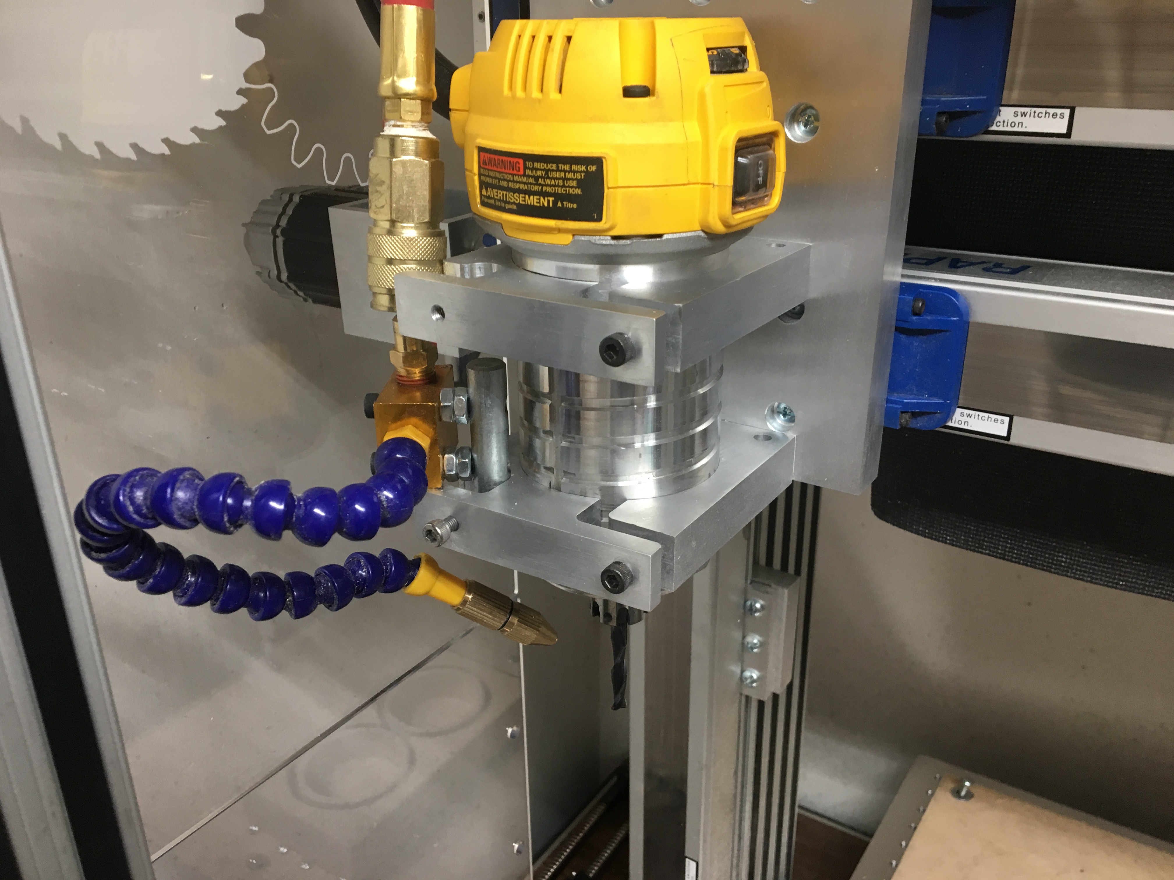
You'll also notice that this design is using a router... This turned out to be a mistake, with the DeWalt DWP611 eventually catching aflame. I also have a post about this machine's Spindle Upgrade.
Once the design was complete, I ordered the 80/20 extrusion, servoes, and other parts to get moving with the build.
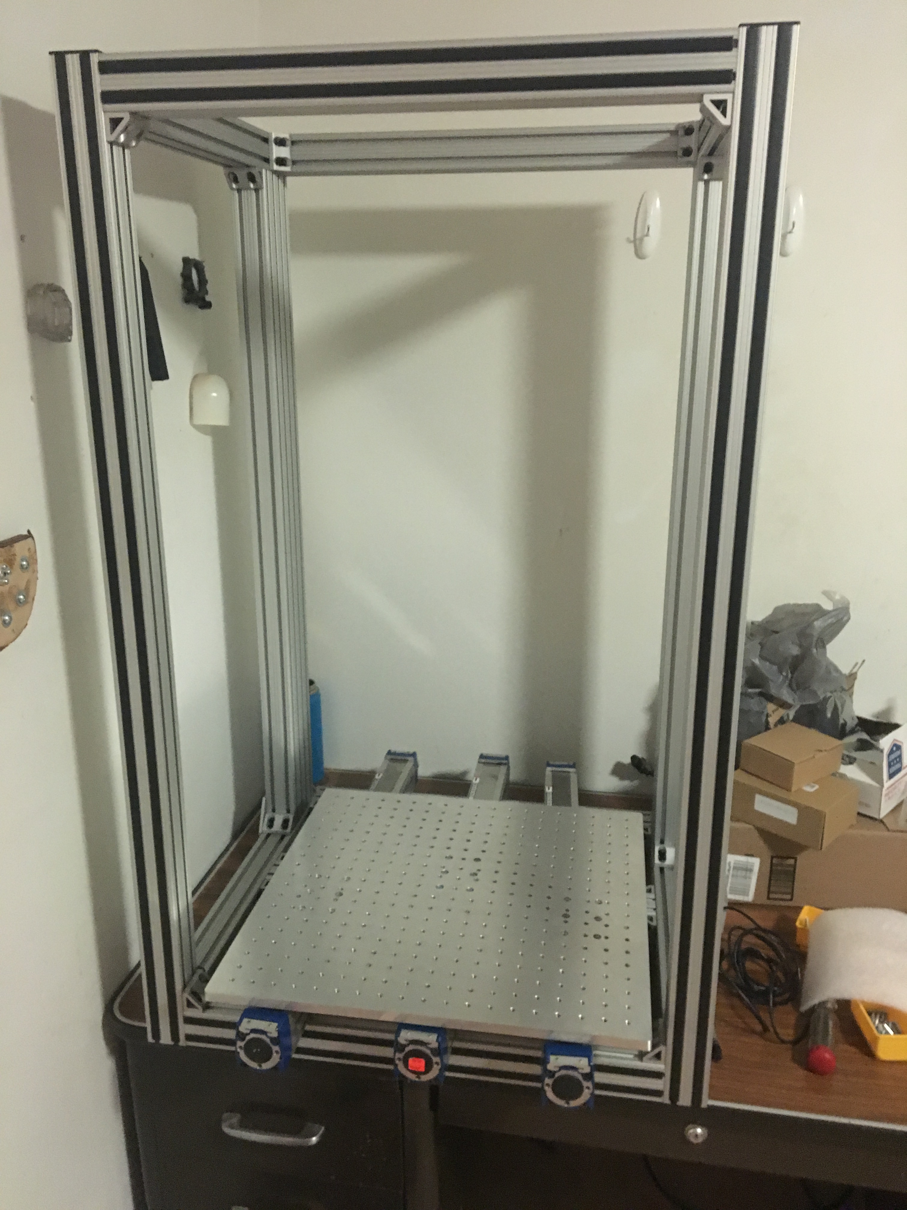
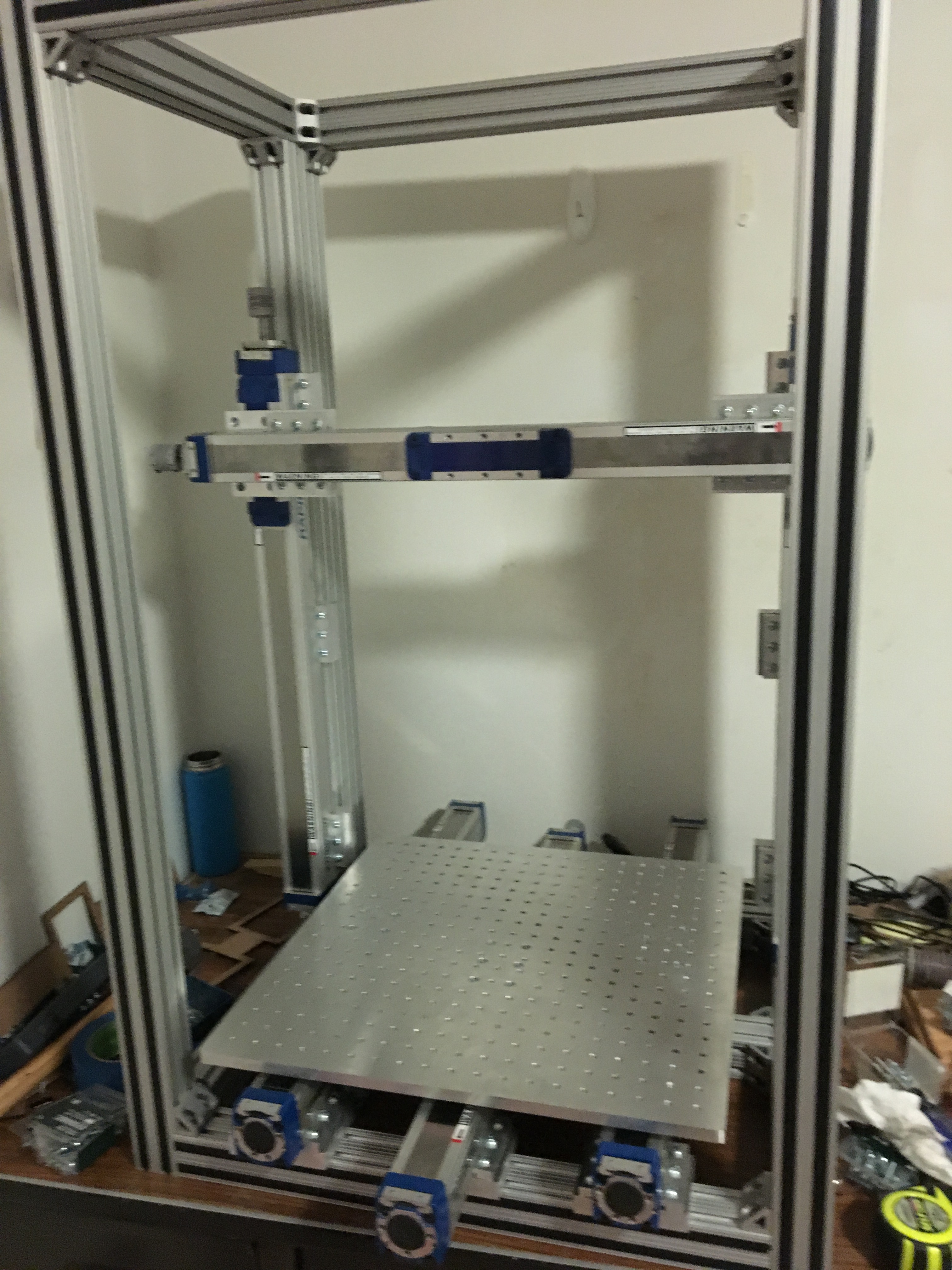
Assembly and Aluminum Parts
The first thing was assembling the frame. Since all the parts were precut straight from 80/20, this was a relatively straightforward task that takes a little bit of time to make sure parts are square or parallel as needed. I also made the large aluminum plate needed for the Y-axis. I started with an oversized Mic-6 (Cast Tool Aluminum) Plate that I cut down with the table saw. I drilled holes on one-inch centers and tapped them with 1/4"-20. For those of you lucky enough to have a CNC CO2 Laser like me, you can cut a template with the laser to make your life A LOT easier.
I made virtually all the aluminum parts using a CNC CO2 Laser (Epilog Helix) to make templates from hardboard, using double-sided tape to secure them to the aluminum. This made it easy to cut more Mic-6 plate to size, and also served as a handy drill-template at the drill press. A note here: if you have a counterbore, start with the larger hole to avoid chatter.
Once all the aluminum parts were made, I was ready to finish assembly. This was just a matter of bolting everything together and maintaining proper alignment. I took my time here, frequently sweeping a dial indicator riding your various axes to make sure that everything is aligned.
Once the frame was togehter, I put the motors and router on. I also added plexiglass sides to try to keep the dust in, and cheap chinese mister. This mister's water line ended up bursting on me, so I later added this mister, which has been working well since.
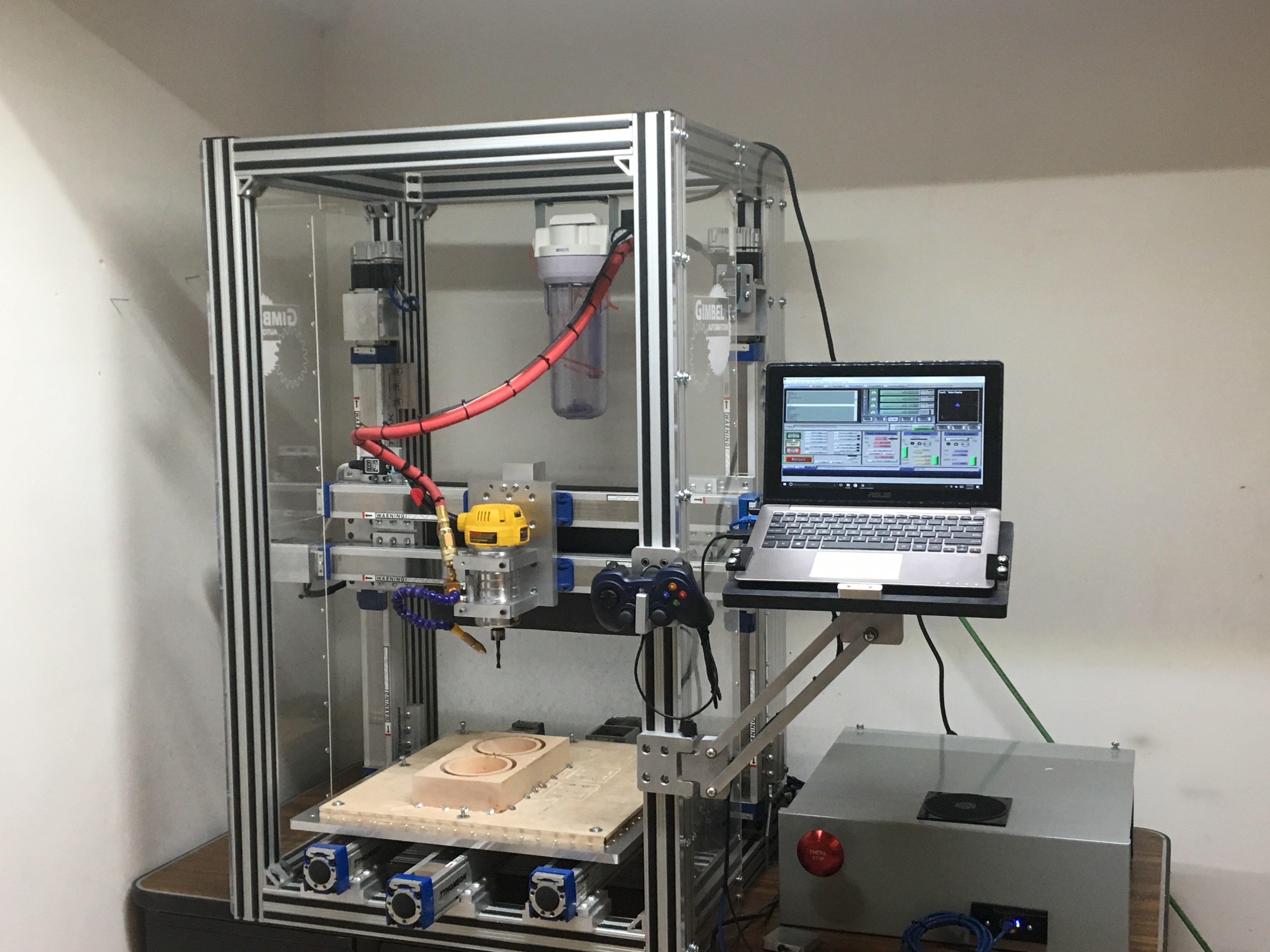
As a final touch, I also made a laptop stand on a parallelogram mechanism. All the parts were machined on this machine, making them the first aluminum parts I made with it. Between the aluminum beams I used Delrin laser-cut washers to prevent galling.
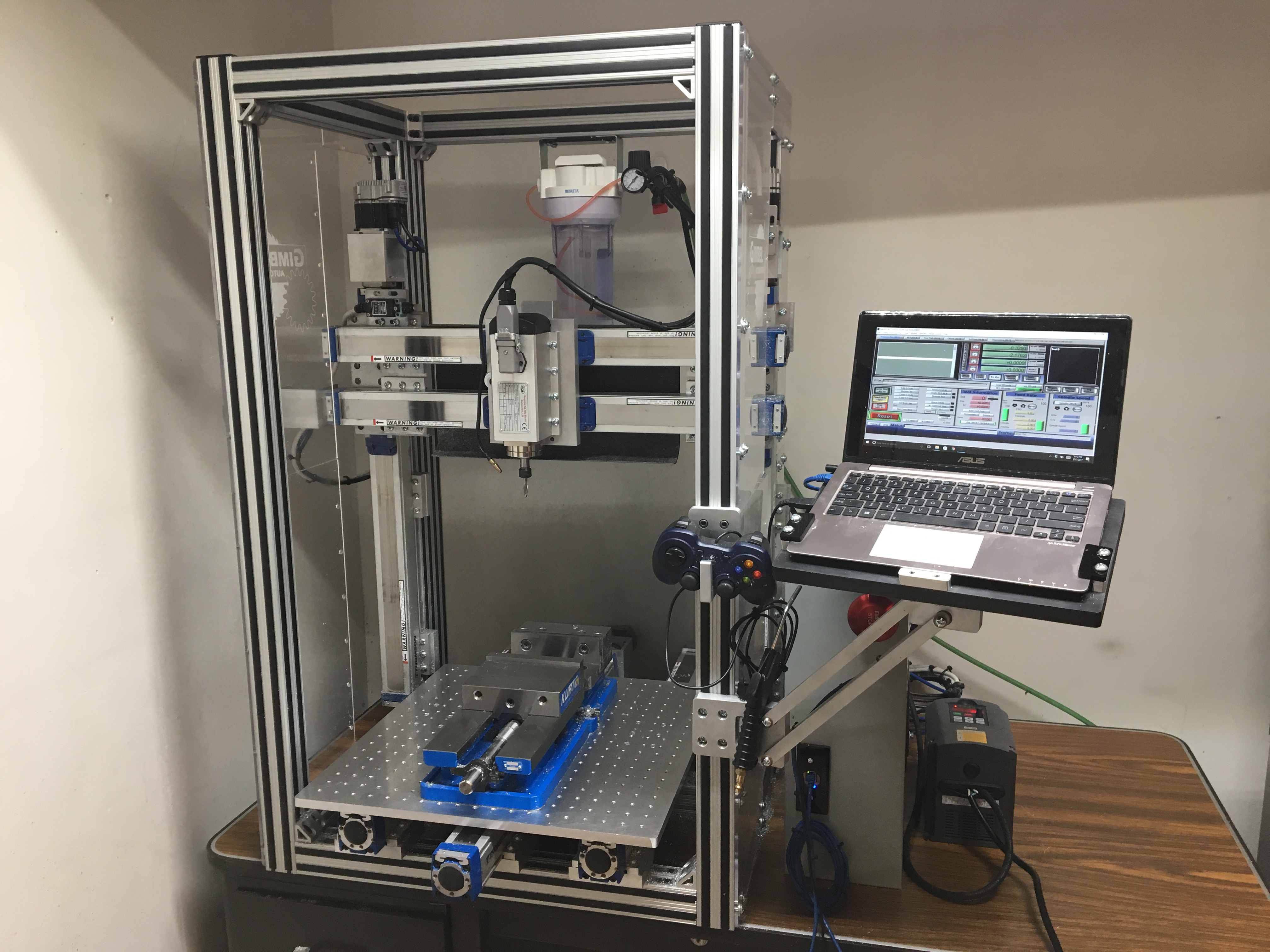
Other Necessities
Along with good chip evacuation, it's critical to have a good workholding solution and high-quality carbide for milling aluminum with a DIY machine. I opted to purchase one of the newer Kurt Vises, which has served me exceedingly well. For good-quality carbide, Lakeshore Carbide is a great source. For coolant storage (I sometimes just use water, to be honest) I am using a Brita Water filter, with the filter removed. I can put additional pressure into the filter cartridge to force additional coolant through if I want an effect more like flood coolant. The machine in its current state, with spindle, can be seen below.